9.2 Building the Solution
This is a fairly complex project and certainly the most challenging one in the book. We will spend a majority of the time assembling and testing this project’s hardware. After the hardware has been tested, we’ll program the Android phone to talk to the IOIO board, the onboard phone’s camera, and the wireless network. Then we’ll write a simple Android client application we can execute from another Android device that will trigger the IOIO board to turn on the PowerSwitch Tail, which will in turn power the electric door strike that unlocks the door. Here are the steps we’ll take to assemble, program, and deploy the Android Door Lock:
-
Attach the JST connector to the Sparkfun IOIO board so that the IOIO board can be powered by the 5V power supply.
-
Tether the Android G1 phone to the IOIO board via the USB cable.
-
Plug the Smarthome Electric 12VDC Door Strike into the 12V power supply via the 2.1mm female barrel jack cable.
-
Connect the PowerSwitch Tail to the IOIO board via three wires for the PowerSwitch Tail’s power, control, and ground connectors.
-
Program the Android phone to trigger the PowerSwitch Tail via the IOIO board.
-
Snap a photo using the Android phone’s built-in camera when the PowerSwitch Tail is triggered.
-
Send the resulting image as a message attachment to a designated email recipient.
-
Write a native client application for a second Android device that will be used to unlock the door strike.
-
Install the Electric Door Strike in the desired doorframe, routing the electrical wiring to a nearby outlet.
-
Bundle the controller components (the PowerSwitch Tail circuit and the IOIO board) into an easily accessible wall-mounted lock box that can be serviced in case parts need to be replaced.
-
Mount the Android phone running the door lock server application near the entry with the camera lens facing the door so images of those entering can be easily captured.
The most time-consuming aspects are the soldering of the JST right angle connector to the IOIO board and the wiring of the circuit between the IOIO board and the PowerSwitch Tail. Everything else is simply a matter of plugging into the right segment in the series. Essentially, the 5V power supply plugs into the IOIO board, the Android phone plugs into the IOIO via the USB cable, the PowerSwitch Tail, controlled by the IOIO board, plugs into the wall on one side and the 12V power supply on the other, and the electric door strike plugs into the 12V power supply.
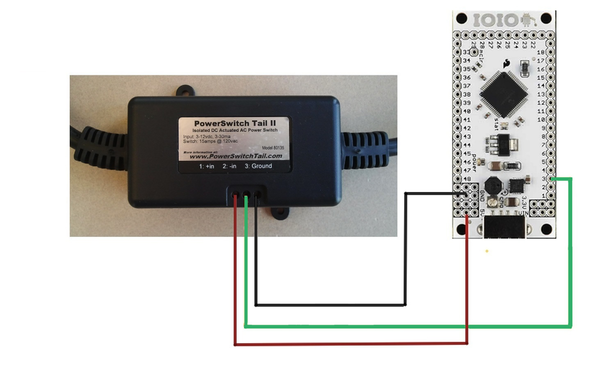
Figure 38. Android Door Lock wiring diagram
The first thing you should do is solder the JST right angle connector to the IOIO board. It would have been much easier for Sparkfun customers had the connector been preinstalled on the board. But hey, that’s part of the fun (along with the terror should something go horribly wrong when an expensive component accidentally gets fried) that these projects have to offer. Fortunately, soldering the connector isn’t too difficult and will make powering the board and the Android phone vastly easier.
After the JST connector is attached to the IOIO board, plug the barrel jack to 2-pin JST cable into the JST connector on the board and the 5V power supply. Then attach the Android phone via a USB cable to the IOIO board. You’re halfway there!
Attach the positive and negative wires of the electric door strike to the positive and negative leads of the 2.1mm female barrel jack cable. The positive wires are those with a white strip along the side of the wire casing. Use electrical tape or, better still, heat shrink tubing to safely cover any exposed wire. Connect the barrel jack to the 12V power supply.
Test the strike by plugging the 12V power supply into your standard 120V wall socket. You should see the LED on the power supply light up, followed by an audible click from the strike. Note that while electrified, you will be able to move the spring latch on the strike back and forth without much resistance. Unplug the 12V power supply from the wall and the strike will return to its fixed, nonelectrified state. Consequently, you should be unable to move the latch.
Next, let’s connect the PowerSwitch Tail to the IOIO board. Follow along with Figure 38, Android Door Lock wiring diagram. Using three wires, connect one from the ground pin on the IOIO board to the the negative lead on the PowerSwitch Tail.
Connect the middle (control) lead on the PowerSwitch Tail to the IOIO board’s digital pin 3. Why not pin 0, 1, or 2? That’s because not all IOIO boards can handle the 5V signal required to electrify the relay in the PowerSwitch Tail. Pulling 5V from a pin not capable of this voltage could damage the IOIO board. Refer to the IOIO board wiki or simply flip the IOIO board over and look for the pins that are enclosed by a white circle.[96] The circle indicates that the enclosed pin is 5V pullup capable. When wired, your IOIO board should look like the one shown in Figure 39, Wiring the IOIO board.

Figure 39. Wiring the IOIO board
Finally, attach a wire from the positive lead from the PowerSwitch Tail to any of the three 5V pins on the left lower corner of the IOIO board. The circuit is complete.
At this point, nothing will happen until we program the necessary instructions to turn pin 3 on and off, thereby signaling the PowerSwitch Tail to do the same. As such, we are going to write a simple Android program with an onscreen toggle switch that will instruct pin 3 to do just that.