8.5 Adding the Sensors
It’s time to combine the working stepper motor with the photosensor we used in the Chapter 5, Tweeting Bird Feeder project. Photosensor readings will be taken every second, and depending on the outdoor light levels, they will trigger the stepper motor to open or close the curtains. We will also add a temperature sensor so that we don’t open the curtains if it’s already too warm in the room or so that we close the curtains if the room temperature exceeds a predetermined level.
Fortunately for this type of project, which relies on the analog pins to measure light and temperature, the motor shield does not use any of the Arduino’s analog pins. Therefore, we will attach one lead of the photocell to the 5V power pin and the other lead to analog pin 0. And just like the Tweeting Bird Feeder project, we need to bridge the 10k ohm resistor from the analog pin 0 to ground. Using a breadboard for this is much easier than wrapping the leads in series. Plus, the breadboard will make a good stand to keep the photocell propped up and angled toward the outdoor light.
The temperature sensor has three leads: the first will connect to the 5V power pin, the temperature sensor’s middle lead will connect to analog pin 5, and the third (far right) lead will connect to the ground pin. The motor shield makes this easier. Refer to Figure 33, Curtain Automation stepper motor and sensor wiring diagram, for setting this up. Note that although the diagram shows an Arduino, the wiring will actually be connecting to the motor shield mounted on top of the Arduino (hence the wiring on the side for the stepper motor connection as well as the wiring to analog pin 5 and the ground and 5V pins on the right side of the shield).
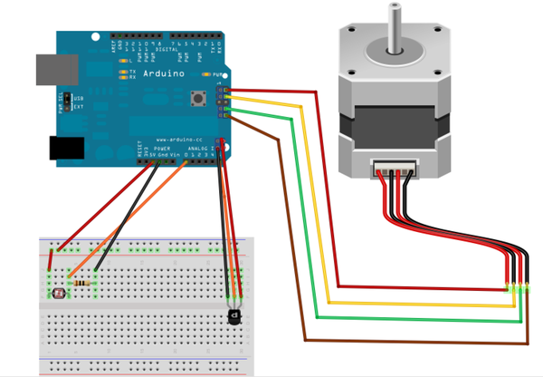
Figure 33. Curtain Automation stepper motor and sensor wiring diagram
We will poll the variable values of these two sensors every second and react accordingly should the threshold values we established for these measurements be exceeded. Let’s write the sketch that will do just that.